Showing posts with label AVR Programmer. Show all posts

Friday, 21 October 2011

ATMEL AVR USB Programmer and Rapid Prototyping Board


PICKIT2 clone


pickit2 components

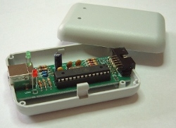
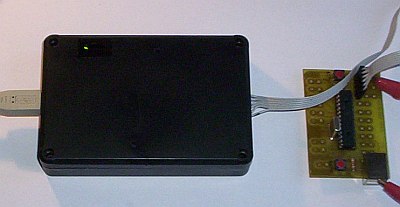
pickit2 with case
PICKIT 2 is simple but powerfull programmer/debugger for Microchip microcontrollers. First firmware/software version was able to debug only one type of microcontrollers, but currently (May 2008) compatibility list is nearly as reach as for ICD2. With latest software package new gadgets were added: simple 3-channel logic analyzer and UART console. Price of original device is also very low.

PICKIT2 scheme (pdf)
Scheme + PCB (Eagle Light)


Tips:
  • After opening .brd file ground plane probably will not be visible - you will see only cut-off polygon (dotted line). Enter "ratsnest" in command line to generate ground plane.
  • To get a printout suitable for PCB etching click View, Display/Hide layers and select (only) layers: Bottom, Pads, Vias, Dimension, Holes, centerDrill.
  • Software and firmware is available at Microchip website. Search for "PICkit 2 v2.55.01 Setup B.zip" or similar archive. Hex file will be copied to application directory. To load firmware for the first time you will need another programmer with ICSP plug, i.e. COM84, connect it to ICSP connecter at the PCB center. Later firmware upgrades will use USB bootloader, so you will probably not need another programmer later.
Revision history:
  • 2008.10.24 Corrected swapped A0 and A2 address pins of EEPROM IC1 (thanks to Achira)
Problems found:
  • LM358 is not a rail-to-rail operational amplifier and if you are experiencing problem vith voltage calibration try to replace it with preferably MCP6002 or similar,
  • target circuit can not draw more than 25 mA; if I try to debug PIC18F4550 with USB on, high core clock, only one LED connected without external power supply I get message "PK2Error 0024 PICkit2 was unable to establish Vdd on the target. (Attempted 5.00V - Read 0.00V),"
  • to debug another circuit I had to configure fusebits (configuration bits) manually in source code (watchdog OFF, LVP OFF); with default fusebits or when I let MPLAB PICKIT 2 plugin to change them debugging failed with message "PK2Error 0028 Unable to enter debug mode" (example for PIC18F2550).
PIC, PICkit2, ICD2 and others are registered trademarks of Microchip, Inc.

Reade more >>

AVR USB programmer

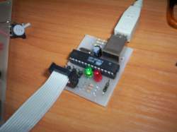
This is a USB in-circuit programmer for Atmel AVR controllers. It simply consists of an ATMega8 and a few passive components. The programmer uses a software USB driver, no USB controller is needed.


Features:
  • Programs most AVR microcontrollers
  • Works under multiple platforms. Linux, Mac OS X and Windows are tested.
  • No special USB controllers or smd components are needed.
  • Programming speed is up to 5kBytes/sec.
  • Works with the programming software AVRDude


Reade more >>

Thursday, 20 October 2011

ATMEL AT89SXX ISP Flash SERIAL Programmer v1.4


HI   Welcome to the world of Microcontrollers,here  first thing you need is a Device Programmer. This In System Programmer use RS232 (serial port)  for communication. 
Hardware
Figure 1 shows  the  Block diagram of the in-system programmer interface,  the programmer can be self powered or target powered it depends on how you plan to use it.


-->


Figure 1:   Block Diagram of the ISP Programmer

Figure 2  shows  the  actual circuit  diagram. The Programmer has just two ICs. IC1 = AT89C2051, IC2 = MAX 232. Few Resistors, LEDs, capacitors etc. The value of the crystal is critical and must be 11.0592 MHz.  


-->


Firmware.

Assemble the circuit and burn the firmware into an AT89C2051(you will need a conventional parallel Programmer to Program the AT89C2051).

Software

The Software is a Windows GUI application and supports all programming functions. When you run the software for the first time it looks for a valid programmer on COM1. If the Programmer is connected to say COM2 you will receive an error message but when the application starts select Options->Settings on the Menu and specify the correct COM Port.
Following are the main features of this software,


  • Device Supported - AT89S51, AT89S52, AT89S8252, AT89S8253.


  • Read and write  Intel Hex files.


  • Chip Erase.


  • Verify.


  • Lock.


  • Read Device Signature.


  • Advanced Device Specific Functions.


  • Download


    AT89SXX ISP Flash Programmer Software   ISP_PROG v1.4.zip
    Firmware for AT89C2051             Firmware v1.4.zip.
    Reade more >>

    USBasp PCB


    USBasp PCB


    Hi in this post i would like to share one of my reference about usb programmer
    PCB for amazing AVR programmer with software USB implementation. For detailed description, firmware package and license information look at Thomas Fischl's USBasp webpage.
    Note: I have some problems with long USB cable connection: device doesn't work so well if it's connected to front-side USB socket of my PC - I have to connect it to back panel. Probably cable length is critical - I recommend use 1,8m or shorter USB cable.


    Latest hardware version - files modified 17.04.2008 - added 2 3V6 Zener diodes for better compatibility with some motherboards
    Approximate speed (ATmega32@Really short manual in Polish
    electrical scheme
    routing scheme (mirrored bottom side)
    assembly scheme (four 0805 capacitors with mirrored partname are located at bottom side)
    additional .eps routing file4.9152MHz, file size = 8366B): FLASH programming 3.15kB/s, FLASH reading 4.85kB/s.
    2006.03.17: avrdude-gui (754kB zip) with added usbasp option (sourcecode v0.2.0 and binary, dev-c++ 4.9.9.2-wx-beta-6.8). Thomas Fischl's patched avrdude included.
    2006.04.06 WinAVR project template available.
    2006.05.24 Added info about wrong signature reading and device programming error with low microcontroller operating frequency (i.e. RC 1MHz, just like default for ATmega8) - use jumper 3 in this case.


    2006.12.21 Some modifications to avrdude-gui, avrdude-gui_v0.2.1.zip (652kB):
    • corrected command line for writing fuses (0xAB:m format),
    • "-F Verify the device signature" description changed to "Override signature check"
    • changed component displaying output from wxlistctrl to memo: auto-scrolled, no long line cut, mouse text selection,
    • removed "terminal mode" checkbox,
    • slightly compacted UI,
    • format comboboxes: changed to read-only
    • changed some fonts to courier new (useful i.e. with avrdude verbose output),
    • changed output for readed fuses values from "con" to "[fusename].dat"; I don't think con output has any effect.
    2006.01.03 I had problems with usbasp.2006-09-16.tar.gz + avrdude 5.2, but latest usbasp.2006-12-29.tar.gz with avrdude 5.3.1 seems to work fine. Here is avrdude 5.3.1 compiled for win32 (Cygwin).
    Notice: I undefined HAVE_LIBHID macro, so there could be problem with AVR-Doper programmer if you'd like to use this.
    Notice 2: cygusb0.dll required by avrdude binary made with cygwin = libusb0.dll or libusb.dll, just rename it and place in avrdude or (better) system directory.
    2007.06.22 Added Avrdude 5.4 win32/cygwin (zip 569kB), compiled with default options. If you'd like to build this release on your own, upgrade libusb library package to 0.1.12.1 (avrdude bug #19889).
    2007.12.15 Added Avrdude 5.5 win32/cygwin (zip 558kB) and cygusb0.dll.
    2009.03.18 Added Avrdude 5.6 win32/cygwin (zip 528kB). Notice: if avrdude shows message about not finding device with VID = 0x16C0, PID = 0x05DC but you can see usbasp under device manager and it's VID/PID pair is the same as required by avrdude, update libusb driver to 0.1.12.1 version. You can find both this and older driver version inside usbasp.2009-02-28.tar.gz archive.
    2009.05.10 Added file avrdude_5_6_r815.7z (7-zip 316kB) - avrdude 5.6 z with patch fromRevision 815.
    Using usbasp 2009-02-28 firmware this avrdude version allows to select SPI frequency during programming by -B spi_delay option. SPI frequencies have discrete values, avrdude selects SPI period to value near to requested spi_delay microseconds.
    With small modification in default avr-gcc makefile this version allows fast programming of "fresh" MCUs that have default RC 1MHz clock without touching SCK jumper. If you are loading firmware to more than a few AVR boards in a row than you will definitely this usefull:
    AVRDUDE_FLAGS = -p $(MCU) -P $(AVRDUDE_PORT) -c $(AVRDUDE_PROGRAMMER)
    AVRDUDE_FLAGS += $(AVRDUDE_VERBOSE)
    AVRDUDE_FLAGS += $(AVRDUDE_ERASE_COUNTER)
    # added:
    AVRDUDE_SCK_FLAGS = -B 5
    ...
    # Program the device.  
    program: $(TARGET).hex $(TARGET).eep
     # Set LFUSE, HFUSE to switch to fast MCU clock,
     # i.e. crystal (low SPI frequency is used)
     $(AVRDUDE) $(AVRDUDE_FLAGS) $(AVRDUDE_SCK_FLAGS) \
     $(AVRDUDE_WRITE_HFUSE) $(AVRDUDE_WRITE_LFUSE)
     # Program MCU using fast SPI clock
     $(AVRDUDE) $(AVRDUDE_FLAGS) $(AVRDUDE_WRITE_FLASH) $(AVRDUDE_WRITE_LOCK)
        
    2009.08.17 Added Avrdude 5.8 win32/cygwin (zip 250kB, debug symbols stripped - smaller executable, giveio and .conf included in archive, cygusb0.dll 0.1.12.1 required).
    2010.04.11 Added Avrdude 5.10 win32/cygwin (zip 263kB, debug symbols stripped - smaller executable, giveio and .conf included in archive, cygusb0.dll 0.1.12.1 required).
    * New devices supported:
          - AVR32A0512 (JTAGMKII only)
          - ATmega32U4
          - ATtiny4
          - ATtiny5
          - ATtiny9
          - ATtiny10
      * New programmers supported:
          - BusPirate
          - Arduino
          - JTAGICEmkII and AVR Dragon in PDI mode (ATxmega devices)
          - STK600 and AVRISP mkII in TPI mode (ATtiny4/5/9/10)  
      * Bugfixes
          - see ChangeLog and ChangeLog-2009 for details          
        
    2011.03.23 Added step-by-step compilation description for avrdude / MinGW+MSYS
    USBasp1.jpg USBasp2.jpg
    Reade more >>

    STK200/STK300 with long cable


    STK200/STK300 with long cable

    From my experience some problems with STK200/300 programmer could be solved by adding additional capacitor to minimize SCK line ringing (line with fastest state changing). You can find more suggested programmer modifications at avrfreaks.net.STK200/300 poprawka
    Reade more >>

    USB programmer for Atmel AVR controllers


     USB programmer for Atmel AVR controllers


    USBasp Foto

    USBasp is a USB in-circuit programmer for Atmel AVR controllers. It simply consists of an ATMega88 or an ATMega8 and a couple of passive components. The programmer uses a firmware-only USB driver, no special USB controller is needed.

    Features

    • Works under multiple platforms. Linux, Mac OS X and Windows are tested.
    • No special controllers or smd components are needed.
    • Programming speed is up to 5kBytes/sec.
    • SCK option to support targets with low clock speed (< 1,5MHz).
    • Planned: serial interface to target (e.g. for debugging).

    Download

    Firmware and circuit

    The following packages include circuit and firmware.
    usbasp.2011-05-28.tar.gz (519 kB) TPI support (upcoming release of avrdude will use it), supports programmers with ATMega88 and ATMega8.
    usbasp.2009-02-28.tar.gz (260 kB)
    usbasp.2007-10-23.tar.gz (172 kB)
    usbasp.2007-07-23.tar.gz (176 kB)
    usbasp.2006-12-29.tar.gz (118 kB) Supports programmers with ATMega48 and ATMega8.
    usbasp.2006-09-16.tar.gz (116 kB) New VID/PID!
    usbasp.2005-11-14.tar.gz (175 kB)
    usbasp.2005-07-03.tar.gz (166 kB)
    usbasp.2005-04-21.tar.gz (169 kB)

    Please refer to Readme.txt for details on building, installing and using USBasp.

    Drivers

    On Linux and MacOS X no kernel driver is needed. Windows requires a driver for USBasp:
    usbasp-windriver.2011-05-28.zip (70 kB)

    Software

    Hardware

    Schematic


    please post your comments


    Reade more >>

    Wednesday, 19 October 2011

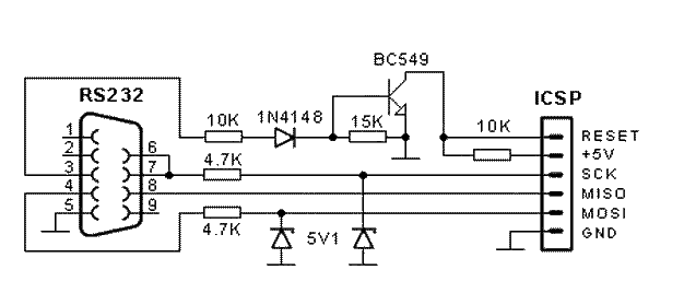
    AVR serial programmer

    Simple AVR serial programmer


    Finished programmer


    Reade more >>

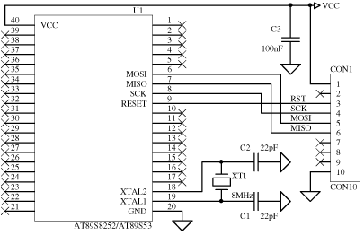
    Atmel core51 microcontroller adapter


    Atmel core51 microcontroller adapter
     
    at89s.gif (10171 byte)
    AT89S8252/AT89S53 connect diagram to base board
    Reade more >>

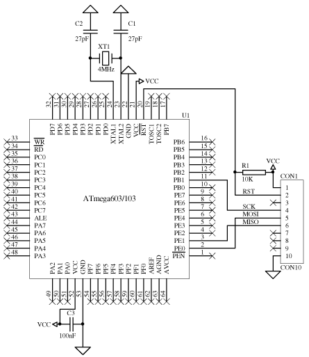
    ATmega103 / ATmega128 adapter

    atmega.gif (19724 byte)

    ATmega103 / ATmega128 connect diagram to base board
    Note that this AVR don't use MISO, MOSI pins for SPI programming, instead use PE0, PE1
    Reade more >>

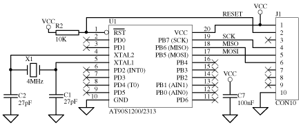
    AVR microcontroller adapter


    AVR microcontroller adapter
    avr20p.gif (5732 byte)


    AVR 20 pin (AT90S1200, AT90S2313) connection diagram


    avr40p.gif (9281 byte)


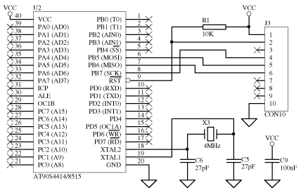
    AVR 40 pin (AT90S4414, AT90S8515) connect diagram to base board


    avr8p.gif (4403 byte)


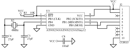
    AVR 8 pin (AT90S2323, AT90S2343, ATtiny12) connect diagram to base board
    Reade more >>

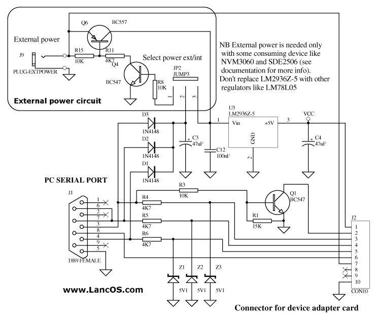
    SI-Prog schematics


    SI-Prog
    schematics


    All schematics in this page are copyrighted © by Claudio Lanconelli, you need my permission before to publish them in your site, magazine or other media.
    Some adapters are not available as GIFs. Look at PDF file, please.
    Complete schematics are available in Acrobat PDF file format:

    SI-Prog 2.2 : current board in production
    NB: AT17Cxx eeprom use the same socket as DS1621 (U10 in the PDF schematics. X2444 use the same socket as 93Cxx (not rotated pinout). MDA2061/MDA2062 are similar to NVM3060, but they also need a 20V at pin 3 and 1KHz clock at pin 13.

    Base board


    SI-Prog base: connect it to the PC DB9 serial port.
    You can connect any of the following adapter card to the 10 pin connector. The interface sinks current from the PC serial port, so it doesn't need any external power.
    Reade more >>

    AVR parallel port programmer

    AVR parallel port programmer


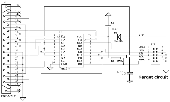
    Schematic


    Reade more >>

    Wednesday, 20 July 2011

    ATTyny 2313 RS232 Board

    ATTiny2313 Board RS232


    Description
    This board is a small controller board on which you can build your projects. It is suited for educational use, experiments or prototyping. The board uses the AT2313 microcontroller with a 10Mhz crystal. The board contains the ISP 10-pin connector for in circuit serial programming. It has also a push button reset switch for resetting the microcontroller. The I/O pins of the microcontroller are also available on two ML10 connectors for connecting for example the LCD-Interface board. The power can be connected via the DC connector which has a pin of 1.1mm. The power regulator supplies the microcontroller with the 5V DC power it needs. The DB9 bus connector can be hooked to the serial port of your PC for communication between the microcontroller and the PC. The MAX232 IC takes care of the voltage conversion of the RS232 voltage levels and the micrcontroller voltage levels.

    schematic


    Layout

    Programming
    The microcontroller on the board can be programmed via the 10-pin ISP connector. The following AT microcontrollers can be programmed with this board:
    • ATTiny2313
    • AT90S2313 (obsolete)
    • AT90S1200 (obsolete)
    •  
    Connector pinout
    In the table below you see the pins of the connectors.
    PORTB pin
    AT2313 pin
    1
    PB0
    2
    PB1
    3
    PB2
    4
    PB3
    5
    PB4
    6
    PB5
    7
    PB6
    8
    PB7
    9
    GND
    10
    VCC
    PORTD pin
    AT2313 pin
    1
    PD0
    2
    PD1
    3
    PD2
    4
    PD3
    5
    PD4
    6
    PD5
    7
    PD6
    8
    NC
    9
    GND
    10
    VCC
    ISP pin
    AT2313 pin
    1
    PB5
    2
    NC
    3
    NC
    4
    GND
    5
    RESET
    6
    GND
    7
    PB7
    8
    GND
    9
    PB6
    10
    GND
    Software
    There are several projects on this site that you can try and use with the ISP-board:
    Partlist
    1
    Bu1
    DC Conn 1,1mm pin
    2
    C1
    47µF 16V
    3
    C2
    100nF
    4
    C3
    100nF
    5
    C4
    100nF
    6
    C5
    1µF 63V
    7
    C6
    1µF 63V
    8
    C7
    1µF 63V
    9
    C8
    1µF 63V
    10
    C9
    100nF
    11
    C10
    100nF
    12
    C11
    100nF
    13
    IC1
    7805
    14
    IC2
    AT90S2313
    15
    IC3
    MAX232
    16
    K1
    ML10
    17
    K2
    ML10
    18
    K3
    ML10
    19
    K4
    DB9 female
    20
    Q1
    10MHz
    21
    R1
    10k
    22
    S1
    Switch
    23
    PCB

    Reade more >>

    adhitz

    Twitter