Showing posts with label 8051 usb programmer. Show all posts

Friday, 21 October 2011

89SXX ISP Programmer using USB interfacing.

89SXX ISP Programmer using USB interfacing.


-->

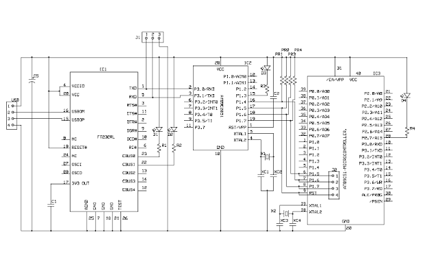


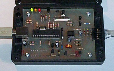
In this circuit power is drawn from usb port itself, so no need of external power supply. Led at the bottom is connected to p2.7 for testing purpose.you can write program to turn on & off the led.led is connected in sinking mode.

1)      Once you are done with USB circuit.Connect the circuit to Computer.
2)      Download Virtual COM Port (VCP) drivers for FT232RL from http://www.ftdichip.com/
3)      For installation Guide of VCP Drivers open “VCP Drivers installation Guide.pdf”
-->

4)      After Device Drivers Installation go to
Control Panel\Hardware and Sound\Device Drivers\
 
                                   click on image to view full size.

-->

After this step open ISP Programmer and configure the COM#  port in “Option>Settings>”

Component List for usb programmer


   click on image to view full size.

    Note:Purchase 8051 of S series only (89's'XX)-40pins DIP 


If you are purchasing components from Mumbai(Lamington Road.) you can program 89C2051 (firmware IC) from VishaKits near GALA.


Click Here to download files.


8051usbprogrammer.rar     (Z-Share)

8051usbprogrammer.rar     (4-Shared)


8051usbprogrammer.rar     (Rapidshare)  


please post your valuable comments..........


Reade more >>

ATMEL AVR USB Programmer and Rapid Prototyping Board


PICKIT2 clone


pickit2 components

pickit2 with case
PICKIT 2 is simple but powerfull programmer/debugger for Microchip microcontrollers. First firmware/software version was able to debug only one type of microcontrollers, but currently (May 2008) compatibility list is nearly as reach as for ICD2. With latest software package new gadgets were added: simple 3-channel logic analyzer and UART console. Price of original device is also very low.

PICKIT2 scheme (pdf)
Scheme + PCB (Eagle Light)


Tips:
  • After opening .brd file ground plane probably will not be visible - you will see only cut-off polygon (dotted line). Enter "ratsnest" in command line to generate ground plane.
  • To get a printout suitable for PCB etching click View, Display/Hide layers and select (only) layers: Bottom, Pads, Vias, Dimension, Holes, centerDrill.
  • Software and firmware is available at Microchip website. Search for "PICkit 2 v2.55.01 Setup B.zip" or similar archive. Hex file will be copied to application directory. To load firmware for the first time you will need another programmer with ICSP plug, i.e. COM84, connect it to ICSP connecter at the PCB center. Later firmware upgrades will use USB bootloader, so you will probably not need another programmer later.
Revision history:
  • 2008.10.24 Corrected swapped A0 and A2 address pins of EEPROM IC1 (thanks to Achira)
Problems found:
  • LM358 is not a rail-to-rail operational amplifier and if you are experiencing problem vith voltage calibration try to replace it with preferably MCP6002 or similar,
  • target circuit can not draw more than 25 mA; if I try to debug PIC18F4550 with USB on, high core clock, only one LED connected without external power supply I get message "PK2Error 0024 PICkit2 was unable to establish Vdd on the target. (Attempted 5.00V - Read 0.00V),"
  • to debug another circuit I had to configure fusebits (configuration bits) manually in source code (watchdog OFF, LVP OFF); with default fusebits or when I let MPLAB PICKIT 2 plugin to change them debugging failed with message "PK2Error 0028 Unable to enter debug mode" (example for PIC18F2550).
PIC, PICkit2, ICD2 and others are registered trademarks of Microchip, Inc.

Reade more >>

adhitz

Twitter