Showing posts with label PC Based Projects. Show all posts

Sunday, 1 January 2012

Led scrolling message display using PIC16f628A

Hi this is my next good one for you

This is a simple led scrolling message display using 16f628a with CD4017 as shift ic ,this project require  simple components for the construction of the display controller  module, so i think it will be very easy to you to construct your self even if you are not well experience in soldering .

COMPONENTS REQUIRED

PIC16F628A    - 1
CD4017            - 4-5nos
24LC256OR 24LC512 - 1
9 pin D female  port - 1
74HC08 - 1
22pf - 2
10MHz crystal - 1
1N4148 or 914 -  5
Red LED - 1
Green LED -1
SPDT switch -1
LED  - depend upon your design
PCB
Soldering iron
etc

Schematic diagram


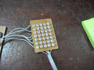
My project under construction


TO DOWNLOAD THE HEX CODE PLEASE CLICK HERE

Project by kajahussain T  thank you


JOIN WITH US ON FACEBOOK 

JOIN WITH US ON TWITTER


Reade more >>

Thursday, 27 October 2011

PIC12F675 Single RGB LED Controller


Hi this is my next good one for you

PIC12F675 Single RGB LED Controller


to download the source code please click here
Reade more >>

Friday, 21 October 2011

MIDI to RS232 Interface


MIDI to RS232 Interface


This is a monodirectional MIDI to RS232 (serial) interface, it play only MIDI to personal PC “RS232″. The MIDI output connector indicated on the left picture  dosen’t work because the buffer inside pic16f84 is too short.


Description

This is a monodirectional MIDI to RS232 (serial) interface, it play only MIDI to personal PC "RS232". The MIDI output connector indicated on the following picture dosen't work because the buffer inside pic16f84 is too short.
Download the archive that contains circuit schema, description and programming files for PICS.

MIDI to RS232 interface

Components:

  • 8 resistors 10k
  • 4 resistors 220r
  • 1 resistor 3k3
  • 4 cond.Tantalie 1uF
  • 4 cond.Ceramic 33pF
  • 1 cond.Elett. 100uF
  • 1 cond.Elett. 10uF
  • 1 1n4148
  • 2 PIC16F84A / 20 (20=max20mhZ)
  • 1 7805
  • 1 MAX232
  • 1 6n136
  • 1 connector 9pin type CANON male (rs232)
  • 2 outlet female DIN180° (midi)
  • 1 cable null-modem standard for PC connection (2x 9pin female):
    • 2 - 3
    • 3 - 2
    • 5 - 5

pic16f84a connections:

  • 1pic16F84A/20 2pic16F84A/20
  • PA0 OUT -> RS PA0 OUT -> MIDI
  • PA1 IN <- RS PA1 IN <- MIDI
  • PA2 DIRECT <-> PA2
  • PA3 DIRECT <-> PA3
  • PA4 DIRECT <-> PA4
  • PB0 DIRECT <-> PB0
  • PB1 DIRECT <-> PB1
  • PB2 DIRECT <-> PB2
  • PB3 DIRECT <-> PB3
  • PB4 DIRECT <-> PB4
  • PB5 DIRECT <-> PB5
  • PB6 DIRECT <-> PB6
  • PB7 DIRECT <-> PB7
Reade more >>

Wednesday, 20 July 2011

PC based Frequency Meter  


Here is a simple technique for measuring frequencies over quite a wide frequency range and with acceptable accuracy limits using a PC. It follows the basic technique of measuring low frequencies, i.e. at low frequency, period is measured for a complete wave and frequency is calculated from the measured time-period. Cascaded binary counters are used for converting the high-frequency signals into low-frequency signals. The parallel port of a computer is used for data input from binary counters. This data is used for measuring time and calculating the frequency of the signal. The block diagram shows the basic connections of the counters and parallel port pin numbers on 25-pin D connector of a PC (control register 379 Hex is used for input). External hardware is used only for converting the higher frequency signals into low frequency signals.
Thus, the major role in frequency-measurement is played by the software. The PC generates a time-interrupt at a frequency of 18.21 Hz, i.e. after every 54.92 millisecond. Software uses this time-interrupt as a time-reference. The control register of the PCs parallel port is read and the data is stored continuously in an array for approximately 54.9 ms using a loop. This stored data is then analysed bit-wise. Initially, the higher-order bit (MSB or the seventh-bit) of every array element is scanned for the presence of a complete square wave. If it is found, its time period is measured and if not then the second-highest order bit (sixth bit) is scanned. This operation is performed till the third bit and if no full square wave is still found, an error message is generated which indicates that either there is an error in reading or the frequency signal is lower than 19 Hz. Lower three bits of the control register are not used.
When a wave is found, along with its time-period and frequency components, its measurement precision in percentage is also calculated and displayed. Number of data taken in 54.9 ms is also displayed. As stated above, the lower starting range is about 19 Hz. Data is read for approximately 54.9 ms. Thus, the lowest possible frequency that can be measured is 1/.0549 Hz. Lower range depends only on the sampling time and is practically fixed at 19 Hz (18.2 Hz, to be precise). Upper range depends on factors such as value of the MOD counter used and the operating frequency range of the counter IC. If MOD-N counter is used (where N is an integer), upper limit (UL) of frequency is given by UL=19xN5 Hz. Thus for MOD 16 counters UL@20 MHz, and for MOD 10 counters UL@1.9 MHz. Care should be taken to ensure that this upper limit is within the operating frequency range of counter IC used.
Precision of measurement is a machine-dependent parameter. High-speed machines will have better precision compared to others. Basically, precision depends directly upon the


Reade more >>
Control electrical appliances using PC


Here is a circuit for using the printer port of a PC, for control application using software and some interface hardware. The interface circuit along with the given software can be used with the printer port of any PC for controlling up to eight equipment .
The interface circuit shown in the figure is drawn for only one device, being controlled by D0 bit at pin 2 of the 25-pin parallel port. Identical circuits for the remaining data bits D1 through D7 (available at pins 3 through 9) have to be similarly wired. The use of opto-coupler ensures complete isolation of the PC from the relay driver circuitry.
Lots of ways to control the hardware can be implemented using software. In C/C++  one can use the outportb(portno,value) function where portno is the parallel port address (usually 378hex for LPT1) and 'value' is the data that is to be sent to the port. For a value=0 all the outputs (D0-D7) are off. For value=1 D0 is ON, value=2 D1 is ON, value=4, D2 is ON and so on. eg. If value=29(decimal) =   00011101(binary)  ->D0,D2,D3,D4 are ON and the rest are OFF. 


Reade more >>

adhitz

Twitter